
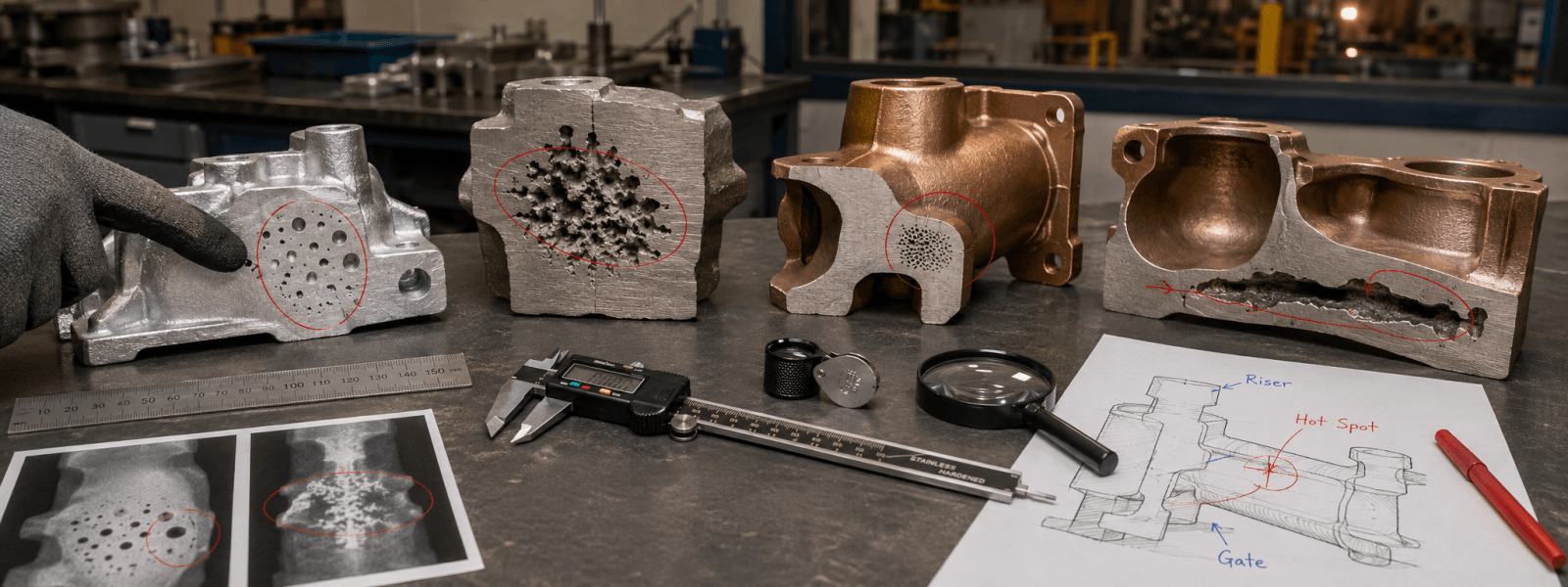
Porosity is one of the most common words used in foundry defect discussions—and one of the easiest words to misuse.
A radiograph shows dark indications. Machining opens a cluster of cavities. A pressure test reveals leakage. Someone calls the defect “porosity,” and the investigation immediately turns toward a familiar corrective action: degassing, venting, changing the riser, lowering the pouring temperature, or adjusting the mold.
But porosity is not a single defect mechanism. It is a result: empty space inside a casting.
That space may have formed because dissolved gas came out of solution, because air or mold gases became trapped during filling, because liquid metal could not feed solidification shrinkage, because oxides or inclusions created favorable sites for pores to form, or because several of these mechanisms acted together.
That distinction matters across aluminum, copper-base, magnesium, zinc, and other non-ferrous castings. Treating every cavity as the same problem can lead to repeated process changes without addressing the actual cause.
Gas Porosity
Gas porosity forms when gas becomes trapped in the casting or comes out of solution as the metal solidifies.
In some alloys, dissolved gas is the primary concern. Molten metal may be capable of holding more gas than the solid metal. As solidification progresses, that gas is rejected from the solidifying structure. If it cannot escape, bubbles may nucleate and grow inside the casting.
Moisture is often involved. Wet charge materials, damp tools, incompletely dried ladles, refractories, molds, cores, fluxes, lubricants, or combustion products can all introduce gas-producing conditions. Furnace atmosphere, holding time, melt temperature, and metal-handling practices may also affect gas pickup.
Other gas defects originate in the mold. Binders, coatings, core materials, lubricants, and moisture can generate gases when they contact molten metal. If those gases are produced faster than they can escape through vents, prints, or permeable mold material, they may enter the metal or prevent it from filling the cavity properly.
Gas pores often appear smooth and rounded because internal pressure shapes the cavity. They may occur individually, as clusters, or as fine pinholes exposed during machining. Their location may provide useful clues. Porosity concentrated near a core, for example, may indicate a different mechanism than pores distributed throughout the casting.
Appearance can guide the investigation, but it does not prove the cause.
Shrinkage Porosity
Shrinkage porosity forms for a different reason.
Metals contract as they cool and solidify. During this contraction, liquid metal must continue feeding the regions that are still solidifying. If the feeding path freezes too soon, or if isolated liquid pockets cannot be replenished, voids remain in the casting.
Shrinkage may appear as a large cavity, a sponge-like region, or fine interdendritic microporosity. It is often associated with heavy sections, isolated bosses, abrupt section changes, poorly fed junctions, or areas that remain hot longer than the surrounding casting.
Unlike many gas pores, shrinkage cavities are often irregular, rough, branched, or dendritic. Their shape reflects the solidifying structure around them.
Shrinkage problems generally require feeding and thermal corrections. The foundry may need to change riser size or location, add chills, modify section transitions, adjust gating, reduce isolated hot spots, or improve directional solidification.
A gas-treatment change will not correct a feeding path that has already frozen.
This is why classification matters. Gas porosity and shrinkage porosity may both appear as cavities on a radiograph, but they point toward different process controls.
Trapped Air and Filling-Related Porosity
Not all gas-related defects originate from dissolved gas or mold materials.
Air can also become trapped during mold filling. Excessive metal velocity, splashing, free-fall, poor venting, abrupt directional changes, poorly positioned ingates, or competing metal fronts may isolate pockets of air inside the cavity.
These defects may occur near high points, blind pockets, thin sections, or regions where multiple streams meet. Their location often follows the filling pattern rather than the solidification pattern.
In pressure-containing castings, even a small interconnected network of trapped-air porosity can create a leak path. The total volume of porosity may be small, but its location and connectivity can make it unacceptable.
Corrective action may involve changing the gating layout, slowing the fill, improving venting, repositioning ingates, changing the mold orientation, or reducing turbulent flow.
Oxides and Inclusions Complicate the Picture
Porosity does not always form independently.
Oxides, dross, slag, sand, refractory particles, and other inclusions may act as nucleation sites for gas pores or interfere with feeding. Entrained films can create internal discontinuities that open during solidification, machining, or service.
This makes the investigation more complicated. A pore may appear gas-related, but poor melt cleanliness or turbulent filling may have created the conditions that allowed it to form. A shrinkage region may also contain oxides or inclusions that interrupted liquid feeding.
In these cases, the defect is not purely “gas” or purely “shrinkage.” It is the result of several interacting variables.
That is common in real foundry work. Defects rarely respect the boundaries of a textbook category.
Microporosity and Macroporosity
Porosity also varies in scale.
Macroporosity is large enough to be visible by eye, exposed during machining, or detected readily by radiography. Microporosity is much finer and may exist between dendrites or within isolated regions of the casting.
Microporosity may be difficult to detect with conventional inspection. It can affect pressure tightness, fatigue life, mechanical properties, machinability, surface finish, and consistency even when no large cavity is present.
A casting can pass visual inspection and still contain damaging microporosity. Conversely, a visible pore in a low-stress, non-pressure area may have little effect on service performance.
This is why acceptance cannot be based on the word “porosity” alone. Size, location, distribution, connectivity, service condition, machining allowance, and inspection requirements all matter.
Start with Evidence, Not Assumptions
A useful porosity investigation begins by describing what is actually known.
Where is the defect located? Is it near a core, a heavy section, a gate, a riser, a surface, or the last region to solidify? Is it rounded, irregular, dendritic, elongated, interconnected, or associated with an inclusion? Was it found by radiography, machining, pressure testing, sectioning, or visual inspection? Is it isolated or repeated? Did it appear after a change in material, tooling, temperature, staffing, maintenance, mold practice, or production rate?
The investigation should then compare the defect with the production record.
Relevant information may include melt temperature, holding time, furnace atmosphere, charge condition, treatment or deoxidation records, mold and core condition, venting, pouring time, gating layout, riser performance, chemistry, inspection results, and recent process changes.
Different inspection methods answer different questions. Radiography may show location and distribution. Sectioning can reveal cavity shape. Metallography can show whether pores are associated with dendrites, oxides, inclusions, or other features. Computed tomography can reveal connectivity. Pressure testing shows whether the defect creates a leak path.
No single test provides the entire explanation.
Keep More Than One Hypothesis Open
The most important habit is to avoid deciding too early.
Rounded pores may suggest gas. Irregular cavities may suggest shrinkage. Porosity near a core may suggest mold gas. Porosity in a heavy junction may point toward feeding. Defects near an ingate may be related to turbulence or entrainment.
But these are working hypotheses, not conclusions.
A late-freezing region may contain both dissolved-gas porosity and shrinkage. An oxide film may support pore formation. Poor venting may combine with excessive filling velocity. A temperature change may affect both gas behavior and feeding.
The investigation should keep multiple explanations open until the evidence separates them.
The Corrective Action Must Match the Mechanism
Porosity does not have one universal fix.
Some cases require better melt treatment or moisture control. Others require improved venting, calmer filling, better melt cleanliness, different risering, added chills, modified section geometry, reduced holding time, tighter temperature control, or changes in mold and core practice.
The right action begins with the right classification.
Calling a defect “porosity” should therefore start the investigation—not end it.
Porosity is not one problem. It is a family of symptoms created by different mechanisms, often interacting with one another. The foundry that takes time to determine which mechanism is actually present is far more likely to make a lasting correction than the foundry that reaches immediately for the most familiar solution.