
Gas Or Shrinkage? Clues That Point You in the Right Direction
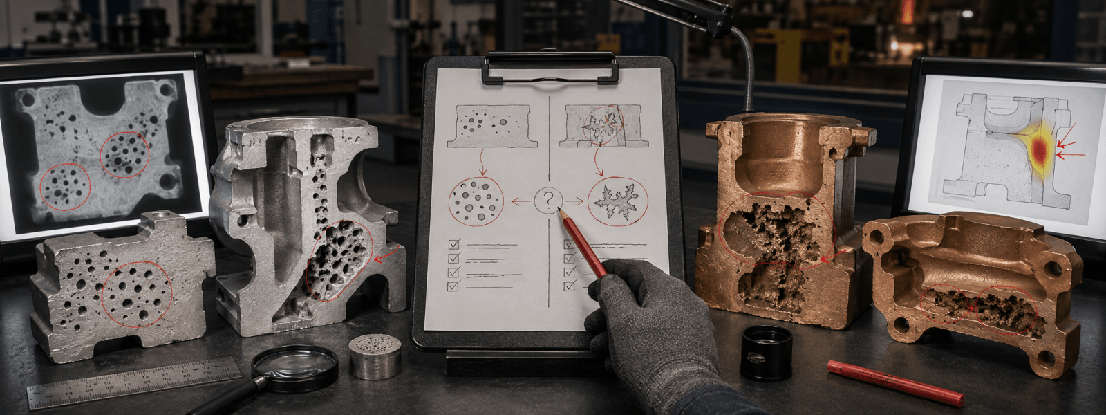
When porosity appears in a casting, the first practical question is often whether the voids came from gas or from inadequate feeding during solidification. The distinction matters because the corrective actions are different. Gas-related defects may point toward melt condition, moisture, mold or core gases, venting, or trapped air. Shrinkage points toward hot spots, interrupted feeding, riser performance, or the casting’s solidification pattern. Applying the wrong remedy can consume time without changing the defect.
Start with the shape of the cavity. Gas pores are often smooth and rounded because internal gas pressure pushes outward against the surrounding liquid or semi-solid metal. On a machined face or polished section, they may appear circular or oval. Shrinkage cavities are more often irregular, angular, branched, or dendritic because they form between growing solid structures when liquid metal can no longer reach the area. Research using metallographic characterization confirms this general contrast, but shape should be treated as a clue rather than proof.
Next, look at location. Shrinkage usually follows the thermal map. It tends to collect in heavy sections, isolated bosses, abrupt section changes, junctions, and other regions expected to solidify last. A defect consistently located in the same hot spot—or beyond the effective feeding range of a riser—should immediately raise a feeding question. Shrinkage forms when solidification contraction cannot be supplied with enough remaining liquid metal, making feeder performance and directional solidification central to the investigation.
Gas-related porosity often follows a different map. Pores near a core, an upper surface, a blind pocket, a poorly vented region, or the meeting point of two metal fronts may suggest mold gas or trapped air. Broadly distributed fine pores may support a dissolved-gas hypothesis. The American Foundry Society defines gas porosity as a condition caused either by gas trapped in the molten metal or by mold gases evolved during pouring. The foundry should therefore distinguish between gas already carried by the melt and gas introduced or trapped during filling.
Distribution also helps. Shrinkage may appear as one concentrated cavity or as a connected, sponge-like network in a late-freezing region. Gas porosity may appear as separated bubbles, clusters, or pinholes. Radiography can show where indications occur, while sectioning, metallography, and computed tomography can provide additional evidence about cavity shape and connectivity. No inspection method should be expected to provide the entire explanation by itself.
Then compare the defect with the process record. For suspected gas, examine melt-treatment results where applicable, charge and return condition, furnace atmosphere, holding time, moisture, ladle and tool drying, core baking, binder or coating condition, venting, pouring turbulence, and the fill pattern.
For suspected shrinkage, review riser size and location, neck dimensions, chills, section geometry, pouring temperature, yield changes, and any simulation or thermocouple evidence showing the final areas to solidify. The physical evidence should agree with the process evidence before corrective action is selected.
Most importantly, do not force every pore into one category. Gas and shrinkage can occur together, and research shows that microporosity may transition between gas-dominated and shrinkage-dominated behavior. Oxides and inclusions can further complicate the cavity’s shape and formation.
The best conclusion is built from several clues: shape, surface, location, distribution, thermal behavior, filling behavior, and production history. Rounded does not automatically mean gas, and irregular does not automatically mean shrinkage. But when the physical and process evidence point in the same direction, the foundry has a much stronger basis for choosing its next action.
The goal is not to name the defect quickly. It is to avoid solving the wrong problem.